Examining the Effect of Angle of Regular Incident Wave in Deep Water on the Force on An Elliptical Vertical Cylinder Using FEM
Mehdi Ardeshiri Lajimi 1 * and Keyvan Sadeghi 2
http://dx.doi.org/10.12944/CWE.10.Special-Issue1.04
Today, a vast range of offshore structures is used in different parts of the world. Computing the force on an offshore structure is one of the first measures for designing the structure and also one of the most difficult steps in the design process. Most of offshore structures are considered as large structures. In these cases, it is used from diffraction theory for computing the imposed force. Using cylindrical elements is common in construction these structures. In this study, the effect of incident wave’s deviation angle on the force on the unit length of one elliptical vertical cylinder located within deep waters examined with finite element method. The obtained results show that the used numerical method had acceptable accuracy and the surge force on the vertical cylinder decreases with deviation angle increasing and consequently the sway force increases.
Copy the following to cite this article:
Lajimi M. A, Sadeghi K. Examining the Effect of Angle of Regular Incident Wave in Deep Water on the Force on An Elliptical Vertical Cylinder Using FEM. Special Issue of Curr World Environ 2015;10(Special Issue May 2015). DOI:http://dx.doi.org/10.12944/CWE.10.Special-Issue1.04
Copy the following to cite this URL:
Lajimi M. A, Sadeghi K. Examining the Effect of Angle of Regular Incident Wave in Deep Water on the Force on An Elliptical Vertical Cylinder Using FEM. Special Issue of Curr World Environ 2015;10(Special Issue May 2015). Available from: http://www.cwejournal.org?p=728/
Download article (pdf)
Citation Manager
Publish History
Introduction
Regarding to development of oil and gas extraction platforms in the country, it is important to correctly and certainly design the structures. The force should be computed correctly for precise designing offshore structures. One of the most important forces on the marine structures is the wave force. Since some marine structures such as oil storage platforms, tankers and or break waters have elliptical or semi-elliptical hulls, it is very important to correctly estimate the force on the elliptical cylinder. The force on marine elliptical structures was previously discussed by the researchers. Analytic and precise solving of the diffraction problem for elliptical cylinder was done (Mei and Chen 1973), Williams presented a semi-analytic solution for the problem with a near approximate method (Williams 1985), Williams and Darwiche considered this problem for an elliptical breakwater (Williams and Darwiche 1985), Recently, Mavrakos and Chatjigeargios have examined the analytic solving of the diffraction problem by an arrays of elliptical cylinders in (Mavrakos and Chatjigeargios 2010).
Today, some numerical methods has been developed for solving the wave diffraction problem of vertical cylinders with different bases, in these methods, the main focus is on more accuracy and efficiency in the calculations and obtained results. One of the common numerical methods for solving such problems is finite element method (FEM) which was used here for examining the effect of incident waves’ deviation angle on an elliptical cylinder.
Governing Equations
It is supposed that there is an elliptical vertical cylinder with the horizontal diameter to vertical diameter ratio of 0.4 . With considering the average of horizontal and vertical diameters as significant diameters and supposing that the vertical cylinder’s significant diameter versus wave length is big enough and also satisfying the conditions of linear wave and diffraction theories, the governing equation on fluid potential in diffraction theory is obtained as follows:
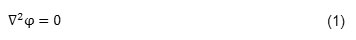
Where φ is fluid potential velocity. Since no water particle is thrown out from a free surface and so there isn’t any vertical flow on the free surface, cinematic boundary condition can be written as follows:
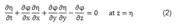
Where y is the vertical motion of free surface. Supposing that wave amplitude is small, so the components of fluid particle velocity and wave steepness are small quantities and thus, the non-linear terms in right hand side of equation number (2) are negligible compared with the linear term. Supposing smallness of wave amplitude allows water level’s boundary condition becomes satisfied in average free surface (zero) instead of fluctuated free surface. As a result, cinematic boundary condition of the free surface becomes linear as follows:
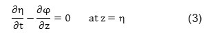
Dynamic boundary condition of the free surface implies that free surface’s pressure should be equal to atmosphere’s pressure. This condition is expressed by Bernoulli equation. In free surface which the relation pressure is zero, this condition becomes linear as follows, by disregarding terms of order 2:
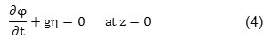
Where g is gravity acceleration. By derivation from the above relation & combining it with (3), the linear boundary condition of fluid free surface is rewritten as follows:
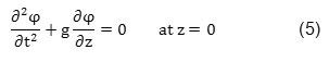
The right component of velocity is zero at seabed level. Levelness of seabed is one common assumption for wave problems. In seabed, there isn’t any vertical flow on the bottom (bed) due to impermeability. So, the boundary condition of the seabed is mathematically written as follows:
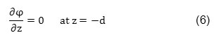
Where z is Cartesian coordinates in vertical direction and d is water depth. If the object is fixed, the fluid particles velocity is zero in vertical direction on the object’s surface. This condition is defined as the following relation:
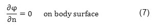
To determine the boundary condition of the long-range scattered waves from the surface, it is enough to use this principle suggesting these waves should be mathematically limited as external waves. Such principle allows the scattered wave’s potential function satisfies the following condition:
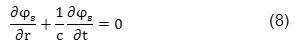
Where φ is the scattered wave’s potential resulted from the object, c is the waves propagation velocity and r is the radial distance from a given point on the object surface. Sommerfeld and Stoker showed that the above relation can be rewritten as following (Sommerfeld 1949) and (Stoker 1957):
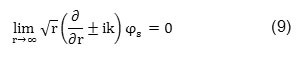
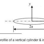
Where k is wave number and i is imaginary variable. Above boundary condition is considered as Radiation or Sommerfeld boundary condition. A simple profile of a vertical cylinder is shown in figure 1.
 |
|
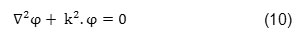
In this project, the force on unit length of a vertical cylinder is computed in average free surface. So, the governing equation on the fluid potential in three domains (Laplace equation) should be converted to a new equation at the free surface. Appling the defined boundary conditions, the equation (1) is converted to the following equation in 2D coordinate system (Helmholtz equation)(Dean and Dalrymple 1991).
The steady potential velocity of the incident wave which reaches to the vertical cylinder under an arbitrary angle α is computed by following relation:
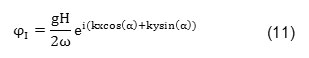
The height of incident wave is considered as 2 meters within deep water.
Finite Element Modeling
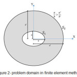
Determining problem domain is the first step in finite element modeling. In this project, the problem domain is on a free surface and starts from a vertical cylinder’s wall. Regarding to Radiation boundary condition, the external boundary of domain should be determined. This was done by applying an ellipse concentric with a vertical cylinder as external boundary. In this way, one equal quantity was added to each horizontal & vertical diameters of the vertical cylinder which led to forming another ellipse. This ellipse’s diameters ratio is less than the vertical cylinder’s diameters ratio. The domain problem is shown in figure 2.
 |
|
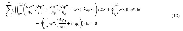
Appling finite element techniques and defined boundary conditions, the weak form of the equation (6) is obtained as follows:

Where w is an element’s weight function. To solve above equation, the problem domain shown in figure (2) became discretized with M 9 nodes elements. So, a direct integration from the equation (12) on the problem domain is divided on the sum of integrals on the surface of each elements[9]. Each partial integral is obtained as a product of each elements’ stiffness matrix in the unknown vector of potential velocity in the nodal points of that element.
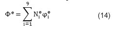
Counter e is the element number and i counter is the number of element’s node. To facilitate solving integration on each element, we used the numerical integration of Guess-Legendre 3×3 and transferring elements and the master element. Finally, assembling equation’s systems from each element leads to obtain the total equations system. In this project, we used four meshes for examining the wave diffraction phenomenon which characterized in table 1.
Table1: The used meshes in finite element method
|
Element number in peripheral direct |
In radial direction |
Element type |
|
|
First mesh |
10 |
3 |
9 nodes quadrilaterals |
|
Second mesh |
20 |
4 |
9 nodes quadrilaterals |
|
Third mesh |
40 |
10 |
9 nodes quadrilaterals |
|
Fourth mesh |
12 |
6 |
9 nodes quadrilaterals |
To estimate the force on unit length of a vertical cylinder by finite element method, firstly the fluid potential velocity of each nodal point on the surface of a vertical cylinder should be computed, the object is obtaining the fluid potential velocity around an elliptic vertical cylinder. A potential velocity includes incident wave’s potential velocity and scattered wave’s potential velocity.
φ = φs + φ1 (15)
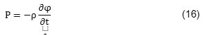
After computing φ1, the fluid pressure on nodal points of a vertical cylinder surface is calculated and then the wave-induced force is obtained by a numerical integration from the pressure on a cylinder’s surface (Sarpkaya and Isaacson 1981):
The best results will be obtained from the smallest mesh. So for summarizing this section, it is only presented the numerical results related to mesh (4). This mesh consists of 720 9-node elements and 1891 nodes. The internal boundary is an ellipse with 1-and 2/5-meter diameters in x and y directions and the external boundary is an ellipse with 5.03- and 6.53- meter diameters in x and y directions. The force on unit length of a vertical cylinder from a wave was considered in five incident angles: 0, 30, 45, 60 and 90 degrees. Meshed domain is shown in figure 3.
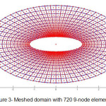 |
Fig. 3: Meshed domain with 720 9-node elements Click here to View figure |
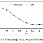
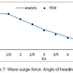
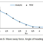
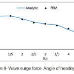
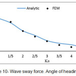
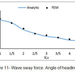
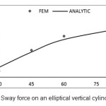
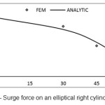
Based on the obtained equations, program called ELLIPTICAL.CYLINDER was written in Matlab software which enables to compute the force on unit length of an elliptical vertical cylinder based on different values of the parameter Ka. Some diagrams related to finite element method are presented in which the obtained results are computed with the analytic results which presented by Mavrakos and Chatjigeargios.
 |
|
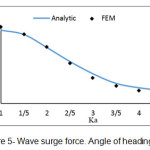 |
Fig. 5: Wave surge force. Angle of heading 30Ëš Click here to View figure |
 |
|
 |
|
 |
|
 |
|
 |
|
 |
|
 |
|
 |
|
Conclusion
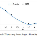
In this study, the force from regular waves on an elliptical vertical cylinder was considered by linear wave theory with finite element method and in different heading angles of incident wave. In this way, 4 different meshes by 9-node elements were used. Based on figures (4) to (11), this method is an accurate and efficient way and has an appropriate adaptation with the present analytic results. Its weak point compared with other methods is the high required time for performing computerized analysis, so using this method in practiced applications seems illogical. According to figures (12) & (13), if the incident wave reaches to the structure with a given angle, surge force value decreases and sway force value increases with increasing wave’s angle of heading; here, Ka is fixed. We should also consider the location of a right cylinder. Here, we selected the big diameter of a right cylinder in direction with axis X. if the short diameter is located indirection with axis X, changing of surge & sway forces becomes inverse. In each wave’s angle of heading, surge & sway force decrease with increasing parameter Ka. In angles of 90Ëš, we can consider the half the domain due to the symmetry in problem geometry, so the required time for performing analysis decreases.
References
- Chen, H. and C. Mei, Wave forces on a stationary platform of elliptical shape. (1972).
- Williams, A.N., Wave forces on an elliptic cylinder. Journal of waterway, port, coastal, and ocean engineering, 111(2): p. 433-449. (1985).
CrossRef - Williams, A.N., Wave diffraction by elliptical breakwaters in shallow water. Ocean engineering, 12(1): p. 25-43. (1985).
CrossRef - Williams, A. and M. Darwiche, Three-dimensional wave scattering by elliptical breakwaters. Ocean engineering, 15(2): p. 103-118. (1988).
CrossRef - Chatjigeorgiou, I.K. and S.A. Mavrakos, An analytical approach for the solution of the hydrodynamic diffraction by arrays of elliptical cylinders. Applied Ocean Research, 32(2): p. 242-251. (2010).
CrossRef - Sommerfeld, A., Partial differential equations in physics. Vol. 1. (Academic press). (1949).
CrossRef - Stoker, J., Water waves, Interscience, New York. (1957).
- Dean, R.G. and R.A. Dalrymple, Water Wave Mechanics for Engineers and Scientists. )World Scientific(. (1991).
- Reddy, J., N, An Int. To The Finite Element. (McGraw-Hill Education) (India) Pvt Limited. (2005).
- Sarpkaya, T. and M. Isaacson, Mechanics of wave forces on offshore structures. )Van Nostrand Reinhold Co(. (1981).